Single Port BMS MOSFETs Explained
Tags: Electronics, Solar
I'm writing this post since it seems there seems to be some confusion on why both MOSFETs in a typical single port BMS (Battery Management System) are controlled individually and why/how this works when they're in the same series circuit. It will hopefully also show why just controlling both MOSFETs at the same time to try and accomplish this is not a good idea.
Let's start with the simplified diagram of a single port, MOSFET based BMS as shown below.
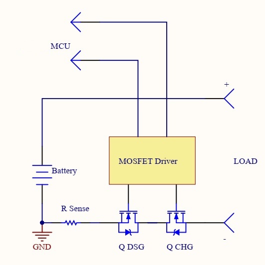
The basics: the load is also where the charger would be connected. R Sense is for the BMS to know how much current is flowing. MCU (Micro Controller Unit) is the controller, and the discharge (Q DSG) and charge (Q CHG) MOSFETs (connected back-to-back) are individually controlled by the MOSFET driver under instruction from the MCU.
Please note that an active MOSFET conducts in both directions. The diodes (body diodes) of the MOSFETs are internal to these devices, and in many applications these are often unwanted (and why they are used back-to-back in bi-directional switch with gates tied together), but they are useful in a BMS where these MOSFETs are controlled individually.
- Suppose we want to both allow charge and discharge. This is easy: enable both MOSFETS and current can flow to/from the battery as needed. Nothing special here.
- If we want to disable both charge and discharge, this is also easy: disable both MOSFETs. Please note that doing so will effectively turn off the battery as you would with a disconnect switch. In other words, any devices that need to know the battery voltage to operate (MPPT, Inverter) will turn off.
So, now we have the issue: what if we hit over voltage protection, or low temperature protection. In both of these instances, we still want to be able to discharge, but not charge. Turning both MOSFETs off won't do since we can't discharge now. The solution is to rely on the internal body diodes:
- To allow discharge, but not charge we turn off the charge MOSFET. In doing so, we still have a current path: through the body diode of the charge MOSFET as shown below.
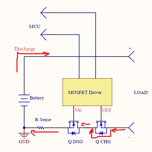
You can see that current flow is one directional only - the diode in the charge MOSFET will be reverse biased for any charge current and thus there will be no current flowing in the charge direction. The inverter and charge controller will still see the battery voltage (minus the drop over the internal diode - typically at around 0.6V).
- To allow charge, but not discharge we do something similar: we turn on the charge MOSFET but turn off the discharge MOSFET as shown below.
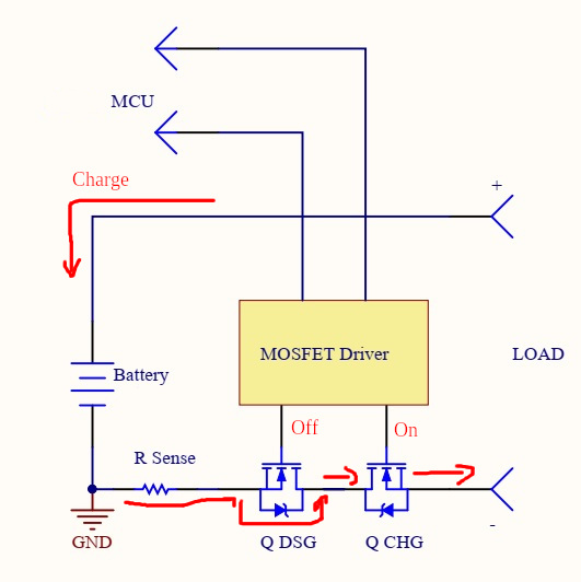
You can see again that the current flow is one direction only: the diode in the discharge MOSFET will be reverse biased for any discharge current and this there will be no current flowing in the discharge direction. Again, the inverter and charge controller will still see the battery voltage (again, minus a small drop).
Now, sending lots of current through this diode is not a good idea. These are far from ideal diodes and they will heat up at relatively low currents. That's where our sense resistor comes in. If the BMS has to only allow charge, as soon as the current builds up (measured to be at 1.5A in a commonly available BMS) the BMS will automatically enable the discharge MOSFET. This will eliminate this diode voltage drop and charging will occur as normal. The same is done if the BMS only allows discharge. As soon as the discharge current rises, the charge MOSFET is enabled to eliminate the voltage drop over its diode.
Note that this process keeps the protections in place: as soon as the current drops again, the relevant MOSFET is turned off again automatically by the BMS.
In conclusion: having the BMS control both charge and discharge MOSFETs independently prevents abrupt battery disconnection in case a problem arises that only affects one of the current directions (charge or discharge). You want to be able to discharge in over voltage, and want to be able to charge in under voltage situations for example. Abruptly disconnecting/connecting the battery in such situations can be detrimental for other devices attached to the battery and indeed the battery itself. Using the internal body diode offers a simple hardware feature to make sure these conditions do not arise.